MBR Color Corrector 3 Manual - Reference
This page describes each option of the MBR Color Corrector 3. If you want a guide to get you started, it is better to look at the main manual.
Overview
MBR Color Corrector works by performing the following calculations in sequence...
Input: The footage is converted to linear RGBColor Correction: The linear RGB information is multiplied by a matrix to correct the colors.White Balance Correction: The linear RGB information is multiplied by a matrix to correct the white balance.Preserve Lightness: The linear RGB information is multiplied by a constant to correct the exposure.Saturation Adjustment: The linear RGB information can have its saturation adjusted by moving the RGB values towards (or away from) gray.Adjustments: The linear RGB information is adjusted by applying a curve to it. (The default curve is to do nothing).Highlight Protection: Any over exposed RGB values are edited to give a more pleasing image.Output: The linear RGB information is transformed into something sensible.
Input
Transfer Function / Color Space
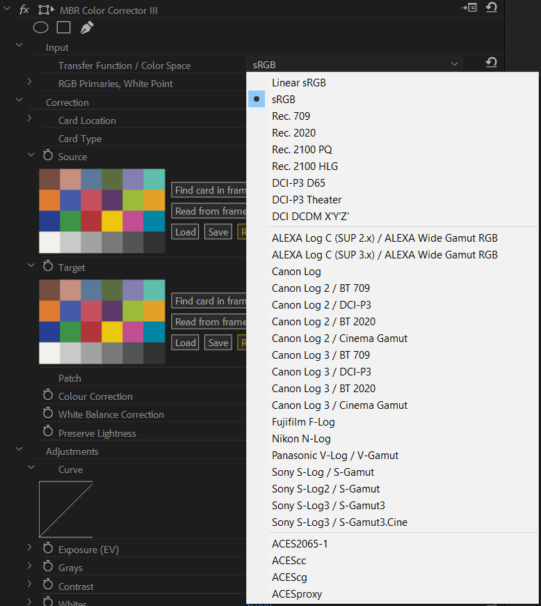
Simply select the option from the dropdown list that matches the settings used on the camera when filming. Usually this is obvious, but sometimes it requires a little more thought as the options may have slightly different names in the camera.
The option Rec. 709 really means
ITU-R Recommendation BT.709
but is often abbreviated as Rec. 709, BT.709, or
ITU709; this means that if the camera has an option called
BT.709
you should select Rec. 709 as the Input Transfer
Function. Similarly: Rec. 2020 or Rec. 2100 may be
called BT.2020
or BT.2100
on the camera.
Some cameras have a HLG / BT.2020
option, for this you should
select Rec. 2100 HLG as the Input Transfer Function.
Hybrid Log Gamma is defined in
ITU-R Recommendation
BT.2100, and the color space for Rec. 2100 is the same as the color space
for Rec. 2020. Therefore the HLG / BT.2020
option is referring to what
the effect calls Rec. 2100 HLG.
The various Canon Log 2, Canon Log 3, and
Sony S-Log 3 options refer to the same transfer function, but with
different color primaries. If you have a shot with the reference card in it; it
really doesn't matter which color primaries you choose as the color correction
based on the reference card patches will correct the primaries. (If you are
correcting a shot without any reference card in it, then
it is important to select the correct color primaries).
RGB Primaries, White Point
You almost certainly want to avoid editing these options...
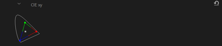
The CIExy control shows where the RGB Primaries and White Point
sit in the
CIE 1931 color space.
These diagrams are commonly found in the specifications / descriptions of the
various standards, for example the
Rec 709 page on wikipedia
includes one in top right.
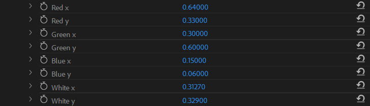
You can change the values for where the red, green, blue and white point are
by editing these eight values. As you edit them the CIExy section
will update to show the new color space, and the Source card will
update to match (if it is a reference card).
These options are most useful with the Linear RGB
transfer function,
for example if you want to use the effect to convert a computer generated
overlay into some display space that you specify in the Output
section.
Correction
Card Location
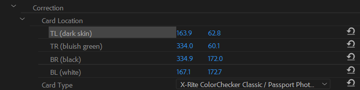
These four options are used to set where the card is in the frame before
using the Read card from frame button in the Source or
Target section.
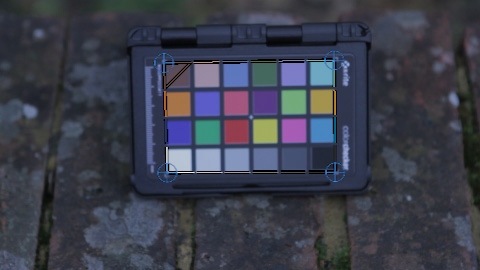
Once you select any of the four corners, the overlay should appear in the monitor. You can now drag the corners the correct location.
The overlay shows a dotted line outlining the area in the frame where the card is. The dotted line is colored to match the patches at the edge of the card, and the top left of the card is marked with a diagonal line, to help mark the card in the correct orientation.
Card Type
Use this option to select which type of color chart you have.
When the Card Type is changed, the Source and
Target options will update to match. If the new card has a
different arrangement of patches, both the Source and
Target will update to a reference card. If the new card has the
same arrangement of patches, then they will only update if they are set to the
reference card.
The following color charts are supported:
 Datacolor SpyderCHECKR
 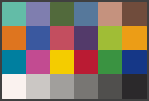 Datacolor SpyderCHECKR 24
 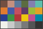 X-Rite ColorChecker Classic / Gretag MacBeth
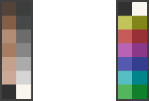 X-Rite ColorChecker Video
 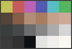 X-Rite ColorChecker Passport Video
  X-Rite ColorChecker Digital SG
 Source, Target, Patch
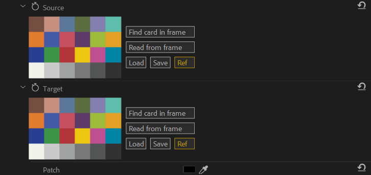
The effect works by calculating how to match the colored patches in the
Source to look like those in the Target.
How you intend to use the effect dictates how you wish to set these two options:
- If you wish to correct some footage:
- set the
Sourcecard to the footage, - and the
Targetcard to the reference card.
- set the
- If you wish to match some footage to some
other footage with the correct look:
- set the
Sourcecard to the footage with the wrong look, - set the
Targetcard to the footage with the correct look. (probably by using the Load button)
- set the
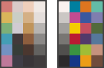
The five buttons to the right of the colored patches do the following:
Find card in frame: This looks in the current frame for the card, and then reads the patches from it into the effect.Read card from frame: This reads the patches from the current frame into the effect. TheCard Locationoptions specify where in the frame the colored patches are read from.Load: This loads the colored patches from a file.Save: This saves the current set of colored patches to a file.Ref: This resets the colored patches to be the reference card. The button is highlighted in yellow if the colored patches are the reference card and the patches are updated to match how the reference card should look for the relevant Transfer Function / Color Space. (theInputoptions are used for theSourcecard, while theOutputoptions are used for theTargetcard).
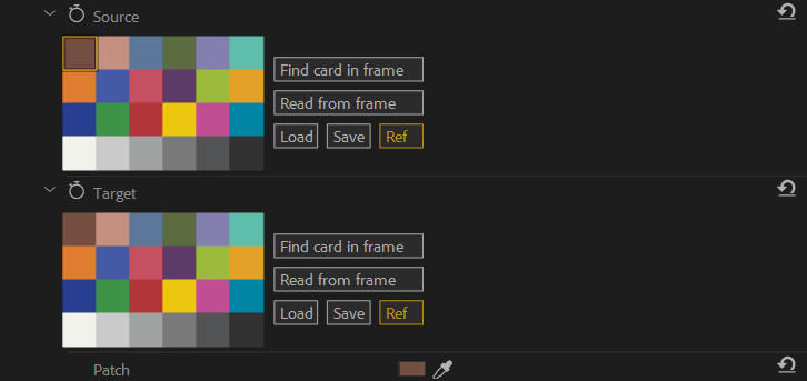
Clicking on individual patch in the Source or Target
option will select that patch for manual editing. Change the Patch
option to update the individual colored patch by hand. (This is very useful
when dealing with a partially obscured
card).
The image on the right shows the top left patch on the Source
card selected (it is outlined in yellow) and ready for editing.
Colour Correction
The Colour Correction option has three settings that control how
the color correction step (see overview) works:
None: This means that the color correction step is skipped.Per Channel: This means that the color correction step multiplies each color channel by a different number to match theSourcecard to theTargetcard.Mix ChannelsThis means that the color correction step calculates a 3x3 matrix to match theSourcecard to theTargetcard.
If the color space is different between the Input and
Output, then the Per Channel selection should not be
selected.
White Balance Correction
The White Balance Correction option selects if the white balance
correction step (see overview) is skipped.
If the option is on: the white and grey patches in the card are used to
calculate a 3x3 matrix to match the white balance of the Source
card to the Target card.
If both the Color Correction and
White Balance Correction are enabled, then you can think of the
color correction as being slightly biased towards getting the white balance
correct (rather than the highly saturated patches).
Preserve Lightness
The result of the color correction and white balance correction steps
(see overview) is that the footage will have the exposure
corrected so that the Source card will have the same
lightness as the Target card.
If the Preserve Lightness option is on: then the exposure
readjusted so that the overall lightness of the footage is unchanged.
Adjustments
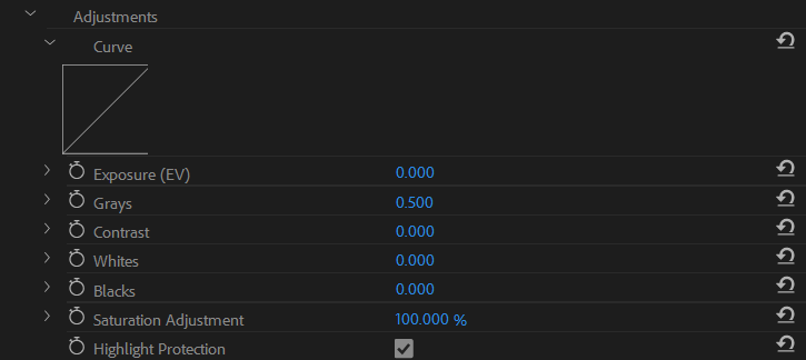
The Adjustments section can be used to apply a simple non-linear
curve to the linear RGB values before they are passed to the Output
section.
If you are converting from HDR / log footage into 'normal' dynamic range, the
Exposure (EV) slider can be very useful to get the correct part of
the footage exposed reasonably.
The default settings only apply Highlight Protection and do not
make any other adjustments.
Curve
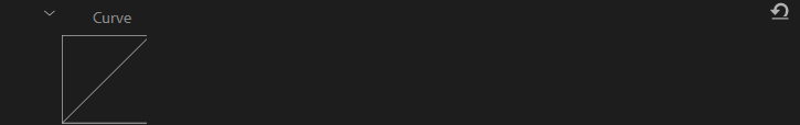
The Curve option shows the curve that results from the
Exposure (EV), Grays, Contrast,
Whites, and Blacks option settings.
Exposure (EV)

The Exposure (EV) option specifies how many stops to make the
image lighter. For example a setting of +2
would make the image 2 stops
lighter (i.e. multiple the linear values by 4).
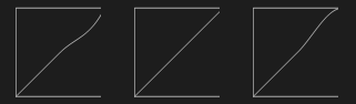
Grays

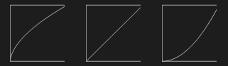
The Grays option specifies which linear RGB value should be
mapped to 0.5. You can think of this parameter as performing the same
adjustment that a gamma curve would.
In the example image, the curves have Grays set to 0.3, 0.5, and
0.7 from left to right.
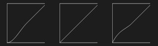
Contrast

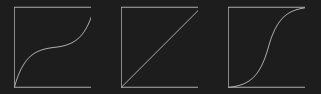
The Contrast adjusts the slope of the curve where the output is
0.5 (i.e. the point specified by Grays).
In the example image, the curves have Contrast set to -10, 0,
and +10 from left to right.
The Contrast option is only enabled in the full version of
the plugin.
Whites

The Whites adjusts the slope of the curve where the output is
1.0.
In the example image, the curves have Whites set to -1, 0, and
+1 from left to right.
The Whites option is only enabled in the full version of
the plugin.
Blacks

The Blacks adjusts the slope of the curve where the output is
0.0.
In the example image, the curves have Blacks set to -1, 0, and
+1 from left to right.
The Blacks option is only enabled in the full version of
the plugin.
Saturation Adjustment

The Saturation Adjustment option allows for tweaking the
saturation of the footage. If the option is set to:
0%the footage will be converted to black and white.100%the footage will be unchanged by thesaturation adjustmentstep.
Highlight
Protection

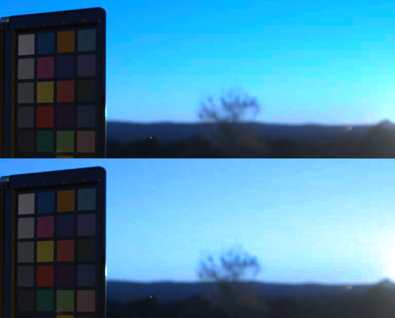
The Highlight Protection option controls how overexposed parts
of the frame are handled.
If the option is off: then the overexposed pixels are passed to the
Output step unchanged.
If the option is on: then the overexposed pixels are adjusted as follows:
- The lightness that the pixel should be (assuming no clipping) is calculated.
- The pixel value is clipped, and the lightness that it now is is calculated.
- Then the pixel is lightened (by adding white) until the lightness matches the lightness calculated in step 1
The sample images are both identical apart from the Highlight
Protection setting, which is off
for the upper image and on
for the lower image.
The Highlight Protection option is only able to be disabled
in the full version of the plugin (the trial version always has it on).
Output
Transfer Function / Color Space
Select the output transfer function based on how you intend to use the footage.
If you don't have a clear idea of which option to pick, you probably want to pick one of the various ITU-R Recommendations as follows:
- For HD footage you probably want to select
Rec. 709. - For 4K footage you probably want to select
Rec. 2020. - For HDR footage you probably want to select
Rec. 2100 PQorRec. 2100 HLG.
Linear RGB
If you are preparing footage to be composited with computer generated footage you probably want to pick one of these options, in all cases the output will be Linear RGB; the difference is the color primaries / white point which are taken from the following standards:
Linear sRGB: those used in the sRGB standard (which are also those used in the Rec. 709 standard).ACES2065-1: the AP0 primaries specified in the ACES standard.ACEScg: the AP1 primaries specified in the ACES standard.
If you need to output any other linear RGB, then you should select any of three options, and edit the RGB primaries and/or white point to suit.
DCI Standards
The DCI-P3 D65 and DCI-P3 Theater options use a pure 2.6 gamma curve and the DCI-P3 RGB primaries, the difference between the two is the white point:
DCI-P3 D65: uses the D65 whitepoint, you may know this standard asDCI-P3 Display
.DCI-P3 Theater: uses a whitepoint with a color temperature of ~6300K.
In either case, you can edit the white point
if needed to generate any other DCI-P3 output
(for example, to generate DCI-P3 D55
, you'd set the White x to 0.33242, and White y to 0.34743).
DCI DCDM
The DCI DCDM X'Y'Z' option can be used to help produce Digital
Cinema Distribution Masters.
- The output is encoded with a pure 2.6 gamma curve.
- The red, green, and blue channels encoding CIE X, Y, and Z values.
- The white point is specified as
equal energy
(i.e. it has CIExy coordinates of 1/3, 1/3).
ACES Standards
Four ACES standards are supported, they have the following intended uses:
ACES2065-1: is linearly encoded, intended to be used for long term storage of footage.ACEScc: is log encoded, intended to be used for footage to be color graded. (This option may be useful if you using MBR Color Corrector to correct the footage, and some other method to grade the footage afterwards).ACEScg: is linearly encoded, intended to be used for compositing with computer generated footage.ACESproxy: is log encoded, intended to be used for transport only. (You probably never need to select this output option).
The ACES2065-1 uses the AP0
color primaries, the other
ACES options use the AP1
color primaries.
The Various Camera Log Standards
You can encode the footage in any of the various supported camera manufacturers log standards.
RGB Primaries, White Point
You almost certainly want to avoid editing these options...
The CIExy control shows where the RGB Primaries and White Point
sit in the
CIE 1931 color space.
These diagrams are commonly found in the specifications / descriptions of the
various standards, for example the
Rec 709 page on wikipedia
includes one in top right.
You can change the values for where the red, green, blue and white point are
by editing these eight values. As you edit them the CIExy section
will update to show the new color space, and the Target card will
update to match (if it is a reference card).
Export LUT

The Export LUT option will save a .cube file that performs the
same color correction as the effect. There are several reasons why you may
want ot do this:
- You have multiple sets of footage that you wish to apply the same color correction to (for example a multi camera shoot, or a shoot with controlled lighting).
- You'd like to generate a LUT to load in to a production monitor.
- You wish communicate a particular look to someone (your color grader), who may not be using Adobe programs.
The Export LUT option is only enabled in the full version of
the plugin.